Board-level Thermal Analysis Goals
- Avoidance of Thermal Failure
- Thermal stress to components
- PCB Delamination
- Study the inter-relationship of current density and Thermal Simulation
- Current Density can increase board temperature
- Board Temperature can increase DC voltage drop
- Apply methods to reduce board and component heat
- Environment
- Airflow
- Ambient Temperature
- Mechanical
- PCB Stack-up
- Component Placement
- Heat Sinks
- Wedge Locks
- Thermal vias
- Thermal Screws
- Environment
Thermal Analysis – Heat Transfer
Modes of Heat Transfer
Conduction: Heat transfer occurs due to direct contact of matter.
Convection: Heat transfer between a solid and nearby fluid in motion.
Radiation: Heat transfer through vacuum. The presence of a medium is not required and heat transfer can happen through empty space.
Thermal Analysis – Inputs Parameters
- In order to perform thermal simulation below parameter are required
- Layout Files and IDF ( Contains Component Height and Outline )
- Power consumption of each device
- Thermal Resistance of devices ( Ɵ Jc – Junction-to-case thermal resistance)
- Thermal resistance of Heat Sink, In case its used in design
- Environment Condition
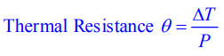
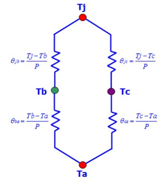
Thermal Resistance
Thermal resistance simply is the opposition offered by the materials involved to the flow of heat energy.
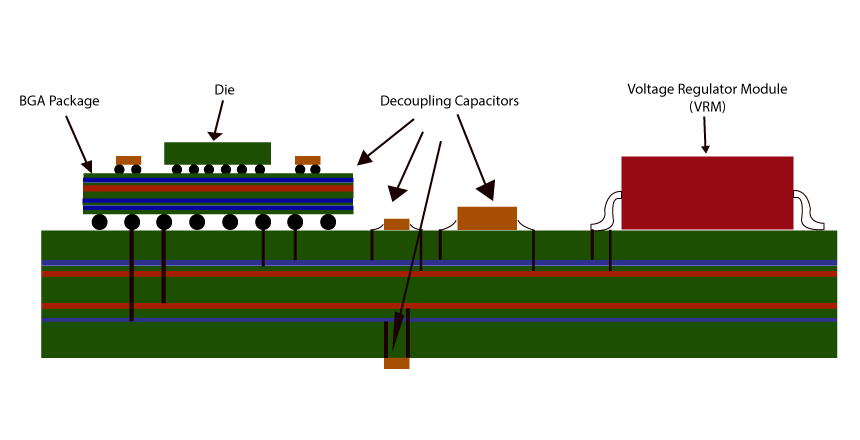
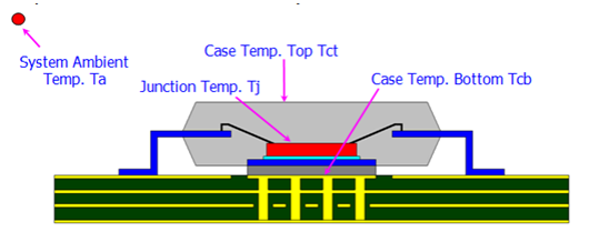
Thermal Resistance Model in Package ( Ɵ JC & Ɵ JA)
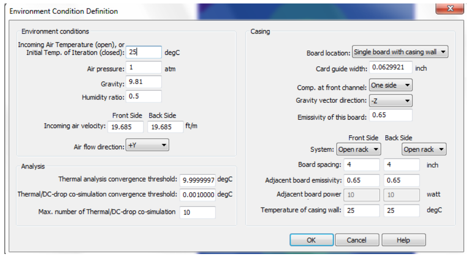
Thermal Analysis- Environment Condition
DC Drop and Thermal Co-Simulation
- Predict effects of high current density on the board temperature
- High Current Density leads to temperature increase on the board
- Co-Simulation uses this to predict temperature increase on the due to high current density on power nets and vias
- Co-simulation between PI and Thermal Simulation engines determine the amount of heat accurately
- Takes into account how heat is conducted on the board
- Includes effects of other heat sources on the board
- Includes the environment board is located in
- Conductivity of copper varies 4% for every 10degC
- Which equates to about 32% over a range of 80degC
- The change in conductivity affects voltage drop and current density
Joule Heating Effect
Joule heating, also known as resistive, resistance, or Ohmic heating, is the process by which the passage of an electric current through a conductor produces heat.
The most fundamental formula for Joule heating is the generalized power equation:
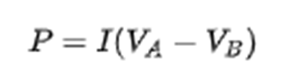
Where,
P = is the power (energy per unit time) converted from electrical energy to thermal energy.
I = is the current traveling through the resistor or other element ( Va –Vb) = is the voltage drop across the element.
(Energy dissipated per unit time) = (Charge passing through resistor per unit time) × (Energy dissipated per charge passing through resistor)
Contact Us: info@sysargus.com
Learning Platform for Product Engineering professionals imparting guidance and sharing knowledge on Electronics System Design Best Practices.
Connect with us:-