Electronic Systems design for ESD Immunity
This article describes different ways to make your electronic equipment and electronic products immune to electrostatic discharge (ESD).
An ESD arc is an intense noise source with significant energy from 1MHz to 500MHz. This energy penetrates your system by every means possible, coupling into cables and printed circuit boards (PCBs), and may cause system upsets, lock-ups, or unwanted resets, as well as lost data and risk of permanent damage.
Many of these techniques can also improve your system’s electromagnetic compatibility (EMC), electromagnetic interference (EMI), and overall robustness.
In the previous Article, we already discussed how to defend against ESD by reducing the coupling into your system, and by making the system immune to transients through the below methods
- Plastic enclosures, air space, and insulation.
- Metal enclosures and shielding.
- Grounding and bonding.
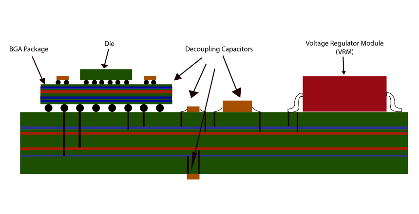
- Power distribution, bypassing, and decoupling.
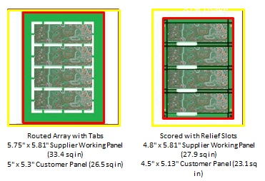
- PCB design and mounting.
- Cable design and routing.
- Filters and transient suppressors.
In the current Article we will discuss how to defend against ESD by reducing the coupling into your system, and by making the system immune to transients through the use of any or all of the following methods:
- Robust components.
- Robust circuit design.
- Watchdog timers.
- Software.
- ESD testing to find and fix weak spots.
Robust Components
Choose robust active components to keep ESD transients from affecting the circuitry:
- Choose active components that:
- Are just fast and sensitive enough to do the job.
- Have enough noise margin that small series resistors on their inputs and outputs will not affect them.
- Have high noise/noise-energy immunity.
- Have good ESD immunity (see Table 2)- upset usually takes about 10% of the damage-threshold voltage.
- Have differential inputs and outputs.
- Can read back all internal registers.
- Are immune to latch-up.
- Don’t push components close to their design limits.
- Test proposed substitute/second- source active components. They may have poorer immunity to ESD upset.
- Prefer processors with fixed interrupt vectors over ones that read the interrupt address from memory.
- Avoid programmable input/output chips. A configuration change can completely change their function.
- Beware of chips with “one-way” instructions- ones that can be reversed only by hardware reset.
Robust Circuit Design
Design circuits such that noise ESD- induced transients cannot cause long-term effects, including upsets, unwanted resets, lock-ups, or lost data:
- Tie unused inputs/bi-directional pins high or low through resistors.
- Avoid edge-triggered logic; latch data with strobes instead of clock edges.
- Do not connect resets, interrupts, or other edge-triggered signals to long cables.
- Do not use circuits that can enter an endless wait/disabled state:
- Halted.
- Waiting.
- Deadlocked.Low-power mode.
- I/O idle mode.
- I/O invalid mode
- Give software control of peripheral chip resets.
- Design peripheral circuits using “hold” or “ready” such that a reset will restore normal operation.
- Give the software a way to hardware reset the entire system, as a last-ditch recovery technique.
- Make sure that ESD transients won’t trigger power monitors.
- Check parity/framing on data whenever you can.
- Use differential signals wherever you can.
- Isolate signals come from the outside world with optoisolators or transformers.
Watchdog Timers
Watchdog timers are circuits that monitor a “heartbeat” generated by the software- this heartbeat stops if the system hangs or the software “gets lost” because of ESD, whereupon the watchdog timer resets and restarts the system:
- Connect the watchdog timer to master reset to force a cold start (all data lost on restart), or to a non- maskable interrupt (NMI) to force a warm start (some data retained on restart).
- Use an edge-triggered input, so that the software must toggle the input to reset the watchdog timer.
- Make sure that software cannot stop the watchdog timer once it has been started.
- Design the software to periodically reset the watchdog timer. This code should be in as few places as possible, and preferably just one spot in the main loop.
- Design the software to run software and hardware sanity checks, including confirming that the watchdog timer is running, before resetting it.
- Choose a period long enough to prevent timeouts when the system is operating correctly, even during rare events, but short enough to prevent danger if the system hangs and must be restarted.
- Use a tight timeout during software testing to ensure that the watchdog timer won’t time out during normal operation.
- Provide a hardware method to disable the watchdog timer (disconnect it from reset/NMI) for product development, ESD testing, and servicing.
Software
It takes a lot of work, but software can be designed to find and correct errors before they become dangerous, including errors caused by random transients like ESD:
- Validate inputs from humans, other software modules, and hardware as soon as you receive them (and recheck them just before use), by checking:
- Type
- Range
- Framing
- Parity/checksum/cyclic-redundancy check (CRC)/Error-correcting code (ECC)
- Acknowledge correct data and return an error code for incorrect data.
- Retransmit data if you don’t receive an acknowledgment.
- Read critical hardware inputs three times, several microseconds apart, and verify that they match before using them.
- Use serial protocols that ignore a single high in a long string of lows and vice versa.
- If a peripheral uses an index register to access internal registers, set the index register just before doing critical reads/writes.
- Don’t let out-of-domain inputs affect program flow.
- Check pointers, indexes, and index registers against the bounds of data structures, arrays, stacks, and heaps before using them.
- Check the count before entering a delay loop.
- Immediately exit with an error if you find that the count is outside its legal range while executing a loop.
- Point all unused interrupt vectors to an error handler.
- Log abnormal events for later analysis.
- Store critical data in multiple locations. Periodically crosscheck these locations and fix mismatched data.
- Break large tables into fixed-length records, each with a checksum.
- Protect blocks of data with parity bits/checksums/CRCs/ECCs.
- Put redundant data (pointers, counts, type/status identifiers) into data structures for easy checking and repair.
- Keep a copy of all output states in memory, and periodically:
- Reread control and selection inputs.
- Refresh configuration registers and output ports.
- Check memory, and correct errors.
- Re-enable interrupts
- To regain control if the program counter “gets lost”, put recovery code between routines, at the end of data tables, and in unused memory, with:
- A group of NOPs (as long as the longest instruction that the processor can execute) followed by a software interrupt, call or jump to an error handler.
- Two absolute jumps/calls to an error handler, located such that the data bytes match the opcode.
- Do sanity checks before exiting a routine. Verify:
- A token that was written before calling the routine.
- Checkpoint flags that are set at critical points in the routine.
- A flow-check counter is incremented in the routine.
- The stack pointer is in a valid range.
- The return address is to a code segment, and a CALL instruction precedes the return address.
- Make sure that the error detection/warm-boot process is fast enough to find and correct errors before the system becomes dangerous.
- Put a multibyte flag filled with mixed 1s and 0s in each volatile RAM as a power-loss indicator.
- Try to restore the last correct state after an error. If this is unknown, go to a safe state, then notify the user and any attached units.
ESD Testing
ESD testing points out weak spots that we have overlooked:
- To work on the hardware’s ESD immunity, run a specially-compiled version of the software:
- With the software ESD-immunity features are disabled.
- That continuously exercises all functions of the system without operator intervention.
- That uses a LED/beeper/status display to warn that an error occurred.
- Have product designers attend or help with the ESD testing.
- Begin with indirect ESD tests, harden the system to that desired ESD-immunity level, and only then start running direct ESD tests.
- Start testing at 2kV, and work up in 2kV steps until you see failures or have exceeded your desired ESD- immunity voltage by 1-2kV:
- Find target points with the ESD gun in continuous/fast-repetition mode using the air-discharge tip. Mark these points with chalk or water-soluble marker.
- Test target points at both polarities before increasing the voltage.
- Zap each target point >=50 times at a given voltage.
- Zap at <= one pulse per second. Slow down if the system uses error detection/recovery and needs to fully recover after an error, or if the system consistently passes the first few times you hit a target point, then consistently fails (you may be charging up something with a high-resistance discharge path).
- Keep run/fail maps that show the voltage/polarity at which each target point fails.
- Check supposedly identical ports early in testing to see if one of them is more sensitive than the rest. Then, concentrate your testing on this port.
- Test the system in both operating and installation configurations, and at all customer-accessible points, including any service areas that the user may access.
- If you have multiple sources for critical chips (microprocessors, and chips driving/receiving off-board signals) hand-pick the chips for your ESD-test system from the leading chip vendors.
- If only a few spots seem to be vulnerable, turn out the lights and zap the system to try to see the discharge path.
- Identify vulnerable cables by disconnecting the cable, or clamping a snap-on ferrite onto the cable next to the connector, and rerunning that section of the test.
- If just one area is failing, try testing another unit:
- Similar symptoms at similar voltages/polarities indicate a design problem.
- Different symptoms indicate a contact/bonding problem, cable position, or a marginal component (maybe damaged by the ESD testing).
- Mock-up shields/gaskets/bonding straps from aluminum foil and copper tape.
- If a certain failure seems to come and go, check the seams and bonds near the target point.
- If you install an ESD fix, but it doesn’t seem to affect the ESD immunity, leave it in place until you have attained the system’s desired ESD immunity. Then you can remove the ESD fixes one by one to determine which one(s) are effective.
- Test software defenses with an emulator. Make random changes (one at a time) to registers, stack-pointers, the program counter, and data in memory, then watch what the system does.
- Save your test system for comparison, in case of field problems arise or production units show a sudden drop in ESD immunity.
| Metal | Electromotive Force (EMF), volts | Resistivity, nano ohm-meters |
| Magnesium | (anodic, corrodes) +2.37V | 42 |
| Magnesium alloys | ——— | 50 – 175 |
| Aluminum | +1.66V | 27 |
| Zinc | +0.76V | 60 |
| Galvanized steel | ——— | 100 – 197 |
| Aluminum alloys | ——— | 27 – 86 |
| Chromium | +0.74V | 132 |
| Cadmium | +0.40V | 73 |
| Mild steel | +0.44V | 100 – 197 |
| Iron | +0.44V | 101 |
| Tin-lead solder | ——— | 145 – 195 |
| Stainless steel | ——— | 560 – 780 |
| Lead | +0.13V | 206 |
| Tin | +0.14V | 126 |
| Nickel | +0.25V | 69 |
| Brass | ——— | 61 – 110 |
| Beryllium copper | ——— | 29 – 115 |
| Copper | -0.34V | 17 |
| Bronze | ——— | 91 – 212 |
| Monel | ——— | 510 – 614 |
| Silver solder | ——— | 22 – 172 |
| Titanium alloys | ——— | 482 – 1700 |
| Silver | -0.80V | 16 |
| Titanium | +1.63V | 540 |
| Gold | -1.50V(cathodic, passive) | 22 |
Table 1: Galvanic Series (in order of decreasing EMF)
| Technology | ESD Damage Threshold (Volts) |
| MOSFET’s | 10 – 200V |
| Recording Heads | 10 – 800V |
| VMOS | 30 – 1800V |
| NMOS | 60 – 500V |
| GaAsFET’s | 60 – 2000V |
| EPROMs | 100 – 500V |
| Laser Diodes | 100 – 1700V |
| JFETs | 140 – 7000V |
| SAW devices | 150 – 500V |
| CMOS | 150 – 3000V |
| Op Amps | 190 – 2500V |
| PIN Diodes | 200 – 1000V |
| DRAMs | 200 – 3000V |
| Schottky Diodes | 300 – 2500V |
| Film Resistors | 300 – 3000V |
| Bipolar Transistors | 300 – 7000V |
| SCRs | 500 – 1000V |
Table 2: Immunity to ESD Damage
Electronic engineers, PCB layout folks, mechanical engineers, and programmers must all cooperate to develop equipment and products with good ESD immunity. This is much easier when ESD immunity is considered throughout the design process, instead of treated as an afterthought.
Contact Us: info@sysargus.com
Learning Platform for Product Engineering professionals imparting guidance and sharing knowledge on Electronics System Design Best Practices.
Connect with us:-