Conducted RF Immunity
- Conducted RF Immunity simply refers to a product’s immunity to unwanted noisy RF voltages and currents carried by its external wires and cables
- RF noise e.g.: digital processing, switch-mode power conversion, will generate RF noise on its external cables.
- Products connected to such equipment will therefore be subjected to conducted electromagnetic disturbances at RF in both differential-mode and common mode on their interconnecting cables.
- A sufficient level of conducted RF noise can cause errors or malfunctions in analog or digital circuits
- Analogue Circuits: measurement errors of thermocouples, resistance thermometers, strain gauges, and microphones.
- Digital Circuits: software suffers from false key presses or control signals, and false resets.
Immunity to conducted disturbance, induced by radio frequency field – IEC61000-4-6
IEC 61000-4-6 relates to the conducted immunity requirements of electrical and electronic equipment to electromagnetic disturbances coming from intended radio-frequency (RF) transmitters in the frequency range of 9 kHz up to 80 MHz. Equipment not having at least one conducting cable (such as mains supply, signal line or earth connection) which can couple the equipment to the disturbing RF fields is excluded.
How does the test work?
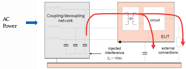
Simplified Equivalent Circuit – The disturbance is applied in common mode with respect to the ground reference plane and therefore generated a current, whose magnitude depends on the EUT’s RF common mode impedance at each port, which flows into and through the circuits within the EUT.
This standard defines:
- range of test levels
- disturbance signal
- test equipment
- equipment verification
- test setup
- test procedure
- test report
Test Levels
No tests are required for induced disturbances caused by electromagnetic fields coming from intentional RF transmitters in the frequency range of 9 kHz to 150 kHz.
Table 1 – Test levels
| Frequency range 150 kHz – 80 MHz | ||
| Level | Voltage level (e.m.f.) | |
| Uo dB (μV) | Uo V | |
| 1 | 120 | 1 |
| 2 | 130 | 3 |
| 3 | 140 | 10 |
| xa | Special | |
| a X is an open level |
Depending on different product standards, test up to 230MHz may required.
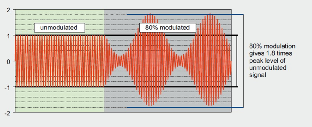
RF noise – amplitude modulated (AM) by a 1 kHz sine wave with a modulation depth of 80 %.
Major Test Equipment:
- Signal Generator
- Power Amplifier and Power
Meter Coupling Devices:
- CDN (Coupling-Decoupling Network)
- EM Clamp
- Current Injection Clamp
- Direct Injection
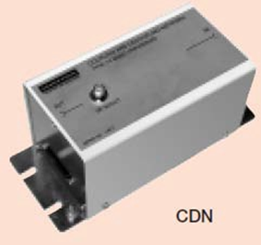
CDN
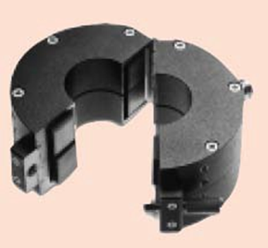
Current Injection Clamp
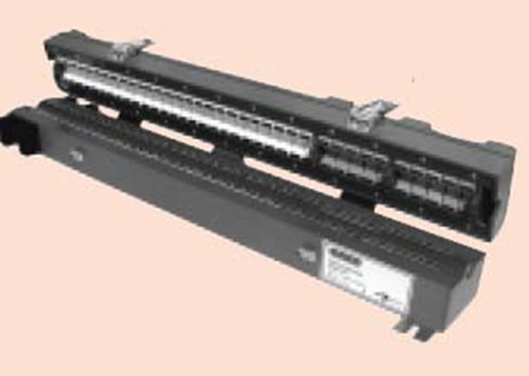
EM Clamp
Test Equipment System – Schematic Diagram
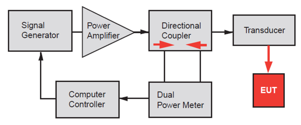
The coupling and decoupling network should provide: –
- coupling of the disturbing signal to the EUT;
- stable impedance, seen from the EUT, independent of the AE common-mode impedance;
- decoupling of the AE from the disturbing signal to prevent interference of the AE; –
- transparency to the wanted signal.
CDN
- M1 – Power supply line 1 line
- M2 – Power supply line 2 line
- M3 – Power supply line 3 line
- T2 – for cable with 1 symmetric pair (2 wire)
- T4 – for cable with 2 symmetric pairs (4 wire)
- T8 – for cable with 4 symmetric pairs (8 wire)
Many other types of CDN are available for a different types of cables
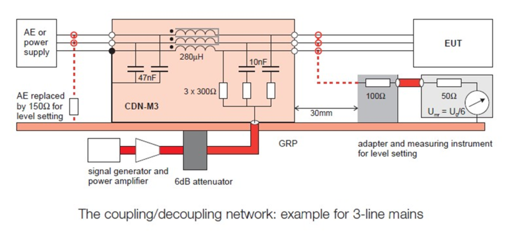
Schematic diagram with CDN-M3
Schematic diagram with EM Clamp
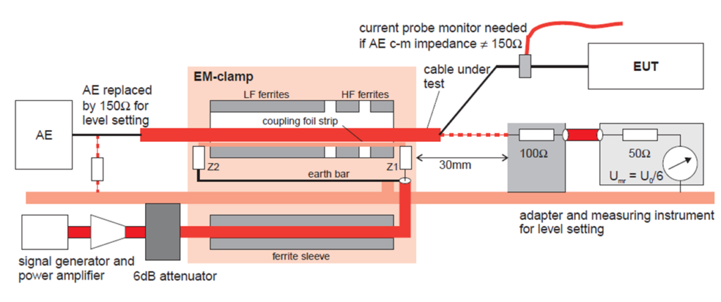
Detail of EM Clamp and Current Injection Probe is in Annex A of the standard
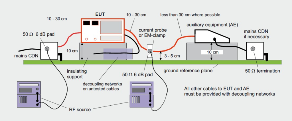
Setup example for EUT with auxiliary equipment
Injection method decision tree:
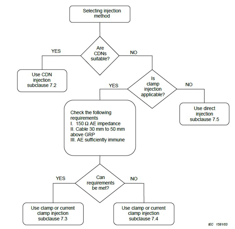
Test setup consideration:
- Ports to be tested
- Setup of CDN injection method
- Setup of Clamp Injection method when common-mode impedance can be met
- Setup of Clamp Injection method when common-mode impedance cannot be met
- Setup of the direct injection method
- Single unit EUT
- Multiple units EUT
Test Procedure
The frequency range is swept from 150 kHz to 80 MHz, using the signal levels established during the setting process, and with the disturbance signal 80 % amplitude modulated with a 1 kHz sine wave, pausing to adjust the RF signal level or to change coupling devices as necessary. Where the frequency is swept incrementally, the step size shall not exceed 1% of the preceding frequency value. The dwell time of the amplitude-modulated carrier at each frequency shall not be less than the time necessary for the EUT to be exercised and to respond, but shall in no case be less than 0,5 s. The sensitive frequencies (e.g. clock frequencies) shall be analyzed separately.
- In practice, carrying out Conducted RF Immunity test can be very straightforward
- The test usually is run by software controlled test system
- For simple household appliances such as washing machines, and refrigerators. etc, test time for once is less than half an hour
- Inject disturbance noise to AC main only
- EUT operation is simple
Basic Immunity Standards: IEC 61000-4
Testing and measurement techniques
HF conducted disturbances
IEC 61000-4-4: – Electrical fast transient/burst immunity test
IEC 61000-4-5: – Surge immunity test
IEC 61000-4-6: – Immunity to conducted disturbances, induced by radio-frequency fields
IEC 61000-4-12: General – High power electromagnetic (HPEM) effects on civil systems
IEC 61000-4-18: Damped oscillatory wave immunity test
Electrostatic discharges
IEC 61000-4-2: – Electrostatic discharge immunity test
LF radiated disturbances
IEC 61000-4-8: Power frequency magnetic field immunity test
HF radiated disturbances
IEC 61000-4-3: – Radiated, radio-frequency, electromagnetic field immunity test
IEC 61000-4-9: – Pulse magnetic field immunity test
IEC 61000-4-10: – Damped oscillatory magnetic field immunity test
IEC 61000-4-20: – Emission and immunity testing in transverse electromagnetic (TEM) waveguides
IEC 61000-4-21: – Reverberation chamber test methods
LF conducted disturbances
IEC 61000-4-11: – Voltage dips, short interruptions, and voltage variations immunity tests
IEC 61000-4-13: – Harmonics and inter harmonics including mains signaling at a.c. power port, low-frequency immunity tests
IEC 61000-4-14: – Voltage fluctuation immunity test for equipment with input current not exceeding 16 A per phase
IEC 61000-4-16: – Test for immunity to conducted, common mode disturbances in the frequency range 0 Hz to 150 kHz
IEC 61000-4-17: – Ripple on d.c. input power port immunity test
IEC 61000-4-27: – Unbalance, immunity test for equipment with input current not exceeding 16 A per phase
IEC 61000-4-28: – Variation of power frequency, immunity test for equipment with input current not exceeding 16 A per phase
IEC 61000-4-29: – Voltage dips, short interruptions, and voltage variations on d.c. input power port immunity test
IEC 61000-4-30: – Power quality measurement methods
IEC 61000-4-34: – Voltage dips, short interruptions, and voltage variations immunity tests for equipment with mains current of more than 16 A per phase
Generic Product Standard
E.g. CISPR24: Information technology equipment Immunity characteristics – Limits and methods of measurement
- IEC 61000-4-2 Electro-static Discharge
- IEC 61000-4-3 Radiated, radio-frequency, electromagnetic field immunity test
- IEC 61000-4-4 Electrical Fast Burst Transients
- IEC 61000-4-5 Surge
- IEC 61000-4-6 Immunity to conducted disturbances
- IEC 61000-4-8: Power frequency magnetic field immunity test
- IEC 61000-4-11 Voltage Dips, Interruption, and Variations
Contact Us: info@sysargus.com
Learning Platform for Product Engineering professionals imparting guidance and sharing knowledge on Electronics System Design Best Practices.
Connect with us:-